 English
  繁體中文
繁體中文  简体中文
简体中文 How to improve from NDX-XXXX?
Technical Instruction:
How to improve the Design and Problems of NDX-3000?
So called alkaline ionized water electrolysis generator has the electrolytic chambers which use drinking water or artificial mixed water supplying the water from bottom and upflow into two rooms separately by the membrane. The water circulating into this two rooms which has the platinum (anode) and (cathode) electrodes formed into alkaline ionized water and acidic ionized water. By using electricity device to separately the water into individually, with DC voltages between 40 V and 120V and The ratio of water volume on acidic ionized water and alkaline ionized water, is at about 1 (acidic ionized water) and 2~3 (alkaline ionized water) which the alkaline ionized water machine is.
I have sorted out the problems of NDX-XXXX which designed and manufactured when I was the President of OMCO (Okazaki Manufacture Co) and the reasons to develop GA-3000, the modified version herein, are summarized and listed as follows.
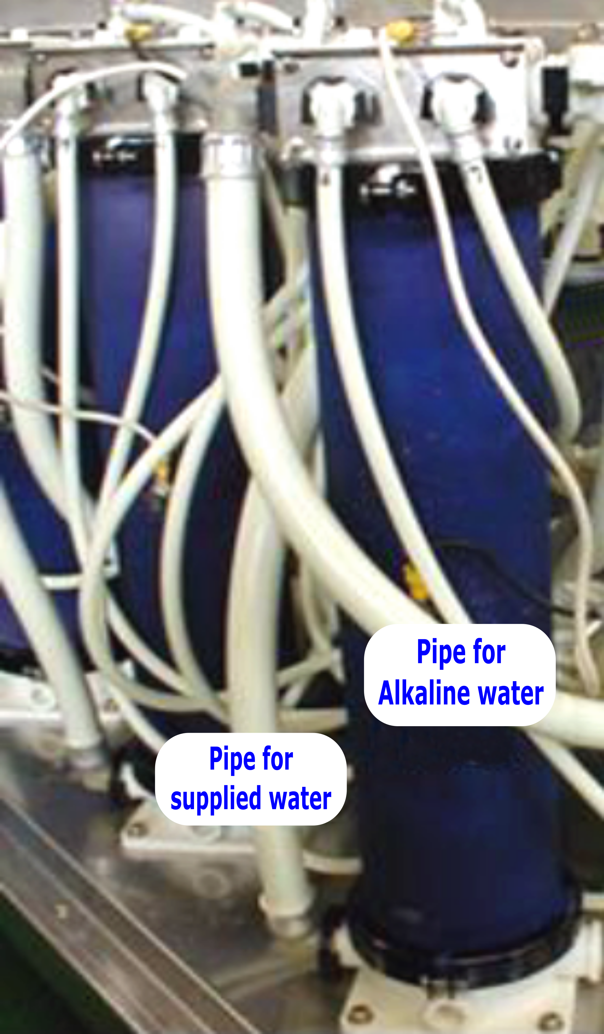
The Model of NDX and GA machines were my design which produces 3,000 litters of alkaline ionized water per hour and is provided with three cylindrical electrolytic chambers. On each electrolytic chamber the NDX-XXXX has installed with four rubber bellows valves which are driven to rotations by the water pressure.
By the certain time electrolysis procedure, the outlet lines of an electrolytic chamber will be switched via bellows valves but the quality of acidic/alkaline ionized water discharged from the water outlets of the electrolysis chambers keeps unchanged
The method of switch valves of NDX-XXXX is , the thin rubber of four bellows valves on each electrolytic chamber (Photo 1: their positions and exteriors) suffered from the water pressure loads after long period of time which will be caused the crack and water leakage. When the rubber bellows valves under water pressure are rotated repeatedly and the switched on the outlet of alkaline ionized water which caused the rubber bellows valves are worsened and cracks which the alkaline ionized water is mixed with the supplied of feed water. This is the defective of structural design on NDX-XXXX.
Moreover, the cam-type control valve has dominating rotations of bellows valves aggravates the deviation of the sliding cam from the shaft and further the abrasion of internal O-rings, all of which may change water pressures applied to close bellows valves on each of three electrolytic chambers on the outlet lines. In defective of this problem, the taste of water will be different slightly when ionized water is mixed with other water.
However, the attributes such as pH values and concentrations of minerals are almost unchanged even if the above problem occurs in NDX-XXXX which fails to detect and shows fault conditions.
The taste of water which depends on a person’s palate only is difficultly differentiated.
In this regard, the taste of electrolyzed water, which consists of activated alkaline ionized water and acidic ionized water, is changed when 100 cc of acidic ionized water is added into 2,000 cc of alkaline ionized water.
For commercialized bottled water, the taste of water should be kept constant. Accordingly, the drawbacks such as troublesome rubber bellows valves for switching water tubes based on a cam should be improved in the electrolysis machine for long-term performance. To produce bottled alkaline ionized water, the electrolysis machine should be reliable on structure. As such, the taste of water from the equipment on manufacture of alkaline ionized water shall be keeping the constant for long time operation. Therefore, the design of some critical components in Model NDX-XXXX needs to be modified.
The structure to switch water tubes on alkaline ionized water and acidic ionized water in Model of GA-3001 and GA-3002 has been improved without any troubles attributed to above abrasion or deterioration.
The details for the theory and the structure of Model GA-3001 and GA-3002 are presented as follows.
By Mr. Tatsuo Okazaki, The Machine Designer
The Valves in Model NDX-XXXX on Switching Water Tubes
|
|
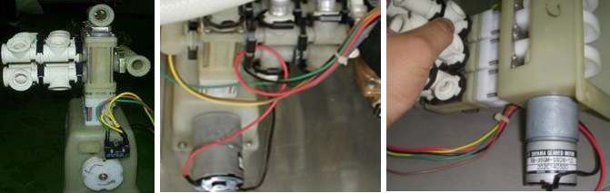
Photo 2: Cam-type control valve to switch bellows valves. Position of the electric switch to regulate the control valve (left); complex tubing (center); cam (right) |


The Modified Valve on the Switching Water Tubes
|
|
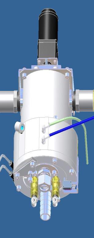
The Display panel of the photo sensor disc on the rotary valve (left); water outlet at the bottom (right) |
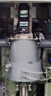 Photo of Rotary valve
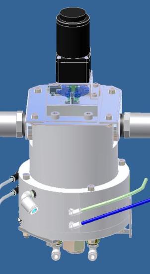
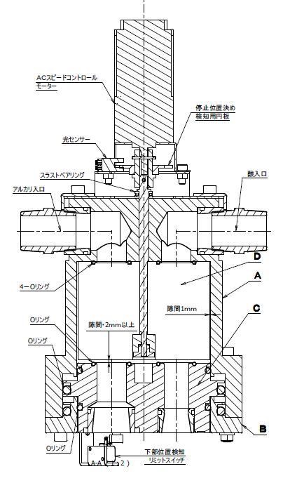 |
As shown in the sectional view of a rotary valve (left), the rotary valve D is installed inside the switching valve body A and the drawing portion C under water pressure is moved flexibly. The O-rings stressfully contact two outlets of alkaline ionized water and acidic ionized water on the switching valve body A to avoid leakage or mixing of water from the rotary valve D and the switching valve body A. The four O-rings mounted on the drawing portion C underneath are fixed by supplied water so that both the drawing portion C and two lines at the rotary valve D communicate with each other at the outlet of the drawing portion C |
| The outlets of alkaline ionized water and acidic ionized water from the electrolytic chamber are modified. Furthermore, the rotary valve D is rotated so that the quality of water from the electrolytic machine is kept homogeneous.
When the rotary valve D is moved downward, some gaps are created and further maintained around the rotary valve D for switching water tubes. After the water tubes are integrated with the rotary valve D and detected by the photo sensor disc at the correct position, the running of the rotary motor is suspended and the drawing portion C from which no fluid leaks is compressed by supplied water. During switching of water tubes, all O-rings which are designed to not contact components will not be worn. Moreover, the rotary motor will not sustain excessive load because of gaps around the rotary valve which is being activated. According to this design, the rotary valve which is being activated for switching water tubes does not contact components, no fluid leaks from O-rings which are compressed with the drawing portion C enabled, and no O-ring is worn. It can be seen from the modified rotary valve that all drawbacks in Model NDX-3000 are overcome |
参考附件:

- Bottled functional water: water manufacturing system for alkaline ionized water, small-molecular water cluster, hydrogen-rich water, high-oxygen water.
- Super Aqua hypochlorous-acid water system, bottle washing, CIP, simple cleanroom, etc.
- OEM/ODM domestic or industrial electrolyzed water generators and hypochlorous-acid water generators.
- Recipes and raw materials for health drinks.


General agency in Taiwan:
SUPER AQUA INTERNATIONAL CO., LTD.
Tel: 886-2-2393-1158 Fax: 886-2-2393-1198
Mobile phone: 886-987-333-287 E-mail: superaqua8899@gmail.com
Address : 8F-8, No. 338, Jingxin St., Zhonghe Dist., New Taipei City 23569, Taiwan